Electric Unscrewing Device
- The highest precision & process reliability
- Shortest cycle-times & highest availability
- Clean & oil-free operation (suitable for cleanrooms)
- Maintenance friendly design – long service intervals
- Compact design
Features
The Clean Solution
Full electric – No Oil – No Leaks. Perfect for Clean Room Facilities.
1 or 2 Gear Box Levels
Systems designed to meet the need.
See It In Action!
Check out video of this device.
Featuring the

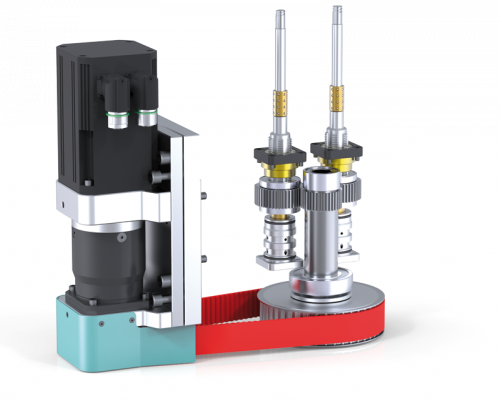
High-performance Servo Unscrewing Devices for Multi-Cavity Molds
Servo unscrewing devices are DME’s answer to the demands made on high-performance injection molds with unscrewing functionality.
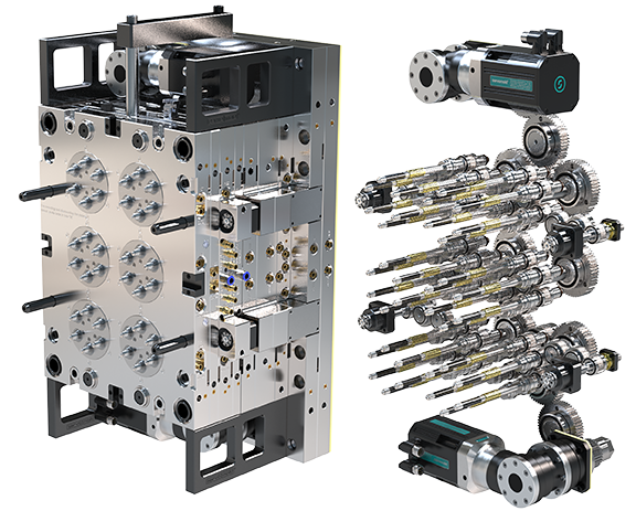
The Clean Solution
for Your Injection Molding Tool.
Specifications
1 to 128 unscrewing concepts
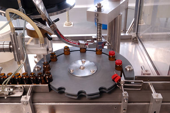
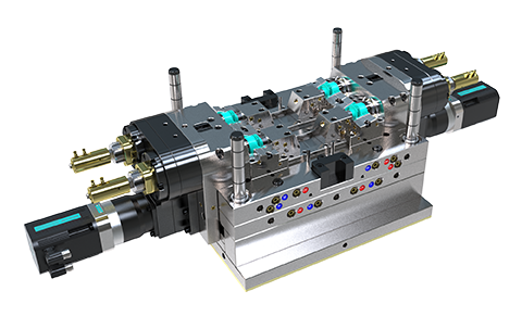
See It In Action!
Featuring

Threaded core, guide thread and cooling insert with sealings.
System Design
1 gearbox level or 2 gearbox levels
- Number of cavities
- Thread size and length and thus maximum breakaway torque
- Cavity spacing and arrangement of the cavities
- Required unscrewing speed
System design is typically handled by project engineers, taking into account the technological possibilities and complying to the customer requirements.
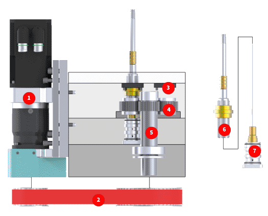
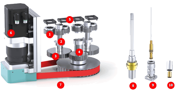
Overview of device includes:
- Ball cage
- Threaded core or threaded sleeves
- Guide nut
- Guide thread
- Servo multi-drive SMA
- Gearbox level 1 with spur wheel
- Gearbox level 2 with timing belt disc, pinion shaft and driving pinion
- Motor plug
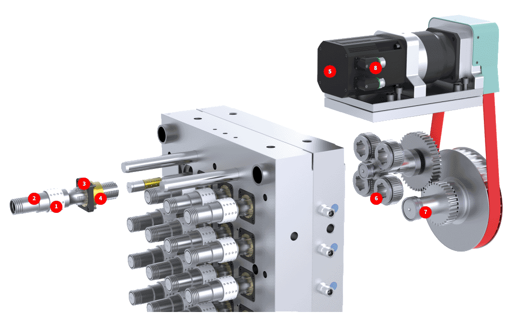
System Design 1 Gearbox Level
In servo unscrewing devices with one gearbox level, several spur wheels are driven by a central pinion shaft RZW. For the design of the system by our project engineers the following information (if available) is needed and applied:
Plastic part
- Thread diameter and length
- Wall thickness and calculated shrinkage
- Type of plastic and fillers
Injection mold
- Maximum tool size and tool height
- The number, layout and desired distance of the cavities
- Threaded cores with cooling
Process
- Mold and melt temperature
- Unscrewing time and overall cycle time
- Cleanliness level (clean zone, clean room)
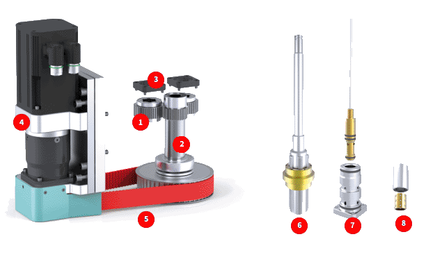
The following figure illustrates arrangement examples of systems with one a single level of gears.
- The cavities can be arranged in a square, rectangular or circular pattern
- Execution of the threaded cores and optional cooling according to customer specification:
- Servo Multidrive SMA
- Servo timing belt unit SZE
- Clamping plate LMP
- Spur wheel STR
- Pinion shaft RZW
- Threaded core set
- Cooling option RKE
The following figure illustrates arrangement examples of systems with one transmission level.

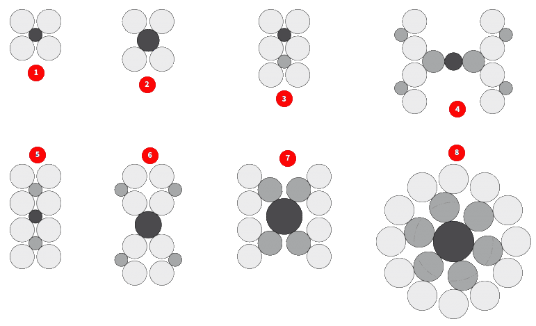
- 4x symmetrical
- 4x asymmetrical
- 6x symmetrical
- 8x asymmetrical
- 8x symmetrical
- 8x asymmetrical
- 8x asymmetrical
- circular
Note: This circular arrangement of pinions is perfect for very compact, high cavity mold design. This can be accomplished with only one gearbox level (8x, 16x). The gating is done with MoldMaster’s Melt Disk.
Sample (Scope of delivery) System Components 4x SAM
- 4x Spur wheel STR incl. bearings
- 1x Pinion shaft RZW incl. bearings
- 4x Clamping plate LMP
- 1x Servo multidrive SMA
- 1x Servo timing belt unit SZE
- Plus 4x threaded core set
- Plus 4x cooling option
- Plus 4x ball cage option
System Design 2 Gearbox Levels
These are coupled with the pinion shafts of the first gearbox level which are driving several spur wheels.
Our Design Engineers can help determine the optimum system configurations for your application using the following parameters:
• Plastic Part • Injection Mold • Process
- 1st gearbox level
- 2nd gearbox level
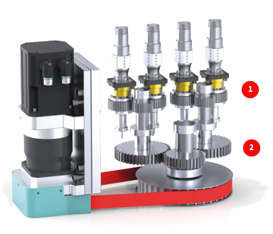
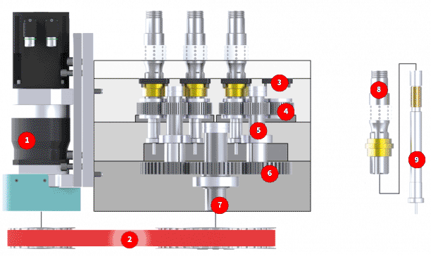
The following figure demonstrates the standard setting for the system design with two gearbox levels.
- The cavities can be arranged in a square, rectangular or circular pattern.
- Execution of the threaded cores and optional cooling according to customer specifications.
- Servo-Multidrive SMA
- Servo timing belt unit SZE
- Clamping plate LMP
- Spur wheel STR
- Pinion shaft 1 RZW-1
- Pinion RTZ
- Pinion shaft 2 RZW-2
- Threaded core set
- Cooling option STI
The following figures illustrates arrangement examples of systems with two levels gears.

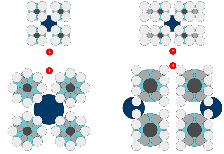
- 16x symmetrical
- 24x asymmetrical
- 32x – circular
- 2x – 8×4 rows
Note: This circular arrangement of pinions is perfect for very compact, high cavity mold design. This can be accomplished with only one gearbox level (8x, 16x). The gating is done with MoldMaster’s Melt Disk.
Sample (Scope of delivery) System Components 16x SAM
- 16x Spur wheel STR incl. bearings
- 4x Pinion shaft RZW-1 incl. bearings
- 4x Pinion RTZ
- 1x Pinion shaft RZW-2 incl. bearings
- 16x Clamping plate LMP
- 1x Servo-Multidrive SMA
- 1x Servo timing belt unit SZE
- Plus 16x threaded core set
- Plus 16x cooling option
- Plus 16x ball cage option
Standard & Special System Sizes
- SAM120144 Z44 M3,00
- SAM080096 Z44 M2,00
- SAM060072 Z44 M1,50
- SAM050060 Z44 M1,25
- SAM040048 Z44 M1,00
- SAM030038 Z36 M0,90
- STR Z20 M1,50
- STR Z24 M1,00
- STR Z32 M0,70
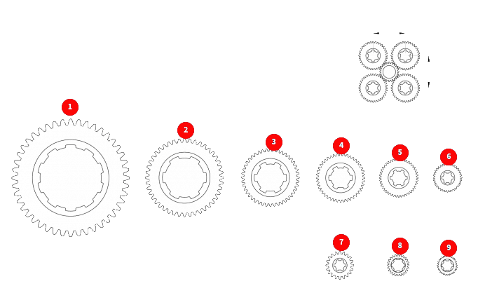
Note: Custom sizes on request!
Want to Know More!
Reach out to DME today.
For all inquires please contact DME at:
[email protected]
Toll-free U.S. – 800-626-6653
Toll-free Canada – 800-387-6600
Worldwide – 248-398-6000
[email protected]
NO MATTER WHAT YOUR NEEDS DME HAS YOU COVERED.


