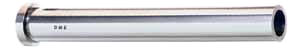
Ejector pins are used in plastics injection molds to eject or push the plastic part from the mold. There are many types of ejector pins, including different materials, sizes, tolerances and coatings, based on the injection mold base application. DME offers high quality ejector pins in all different sizing formats including Imperial, DIN & JIS standards. Our high quality pins are made from premium H-13 steel. We carry straight, shouldered, keyed ejector pins, return pins, sprue puller pins, ejector sleeves & sleeve extensions, ejector blades, core pins & retainers & more!
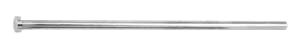
• Made from premium H-13 steel
• Core hardness 47-52 HRC minimizes bending
• Non-chipping surface treatment alleviates flashing and minimizes nicking & dishing - 65-70 HRC
• Annealed and finished heads permit easy machining • Centerless ground D diameter
• Final finish minimizes wear and prolongs pin life
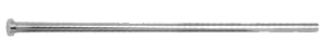
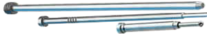
• Precision made of superior quality, thermal, shock-resisting hotwork die steel
• Hot-forged heads provide uniform grain flow, higher tensile strength
• Outside diameter nitrided to 65-74 HRC hardness and finished to minimize wear
• Centerless ground and polished outer diameter
• Precision made of superior quality, thermal, shock-resisting hotwork die steel
• Hot-forged heads provide uniform grain flow, higher tensile strength
• Outside diameter nitrided to 65-74 HRC hardness and finished to minimize wear
• Centerless ground and polished outer diameter
• Precision made of superior quality, thermal, shock-resisting hotwork die steel
• Hot-forged heads provide uniform grain flow, higher tensile strength
• Outside diameter nitrided to 65-74 HRC hardness and finished to minimize wear
• Centerless ground and polished outer diameter
• Inside bearing diameter is 30-35 HRC hardness and finished honed
• Lead-in taper designed to allow interference-free entry of the ejector pin into the sleeve
• ID also available nitride
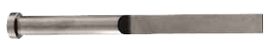
• Blade thickness and width are held to close tolerance: +.0000/-.0003
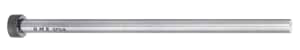
• Precision made of superior quality M2 high-speed tool steel
• Through-hardened to 58-62 HRC for superior wear resistance
• Heads annealed for easy machining
• One-piece construction for increased strength and rigidity
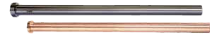
• Precision made of superior quality hotwork die steel
• Pin body and head are finished ground
• +/+ tolerance diameters ensure a close fit for coring purposes
• Available in medium hardness (30-35 HRC) or high hardness (50-55 HRC)
• Performance Core pins are made from Beryllium-free copper-based alloy
• Provide 10x better conductivity
• 90-98 Rockwell B hardness
• Every day, challenging new applications and materials are forcing moldmakers to develop creative new tooling solutions.
• Can't find what you're looking for? Request Special/Custom.
• Special diameters (up to 1.5') and lengths (up to 50'), Step, Profiles, Special shoulders, O-ring grooves, Non-standard core hardness, Flats, Threaded I.Ds or O.Ds, Non-standard materials (non-H13) and Surface coatings.
The purpose of an ejector pin is to apply a force to eject a part from the mold. In some cases this process can leave surface marks known as read-through or pin push. To avoid this the goal of the designer is to position the pins to minimize cosmetic witness marks on your finished parts. Ejector pins are one of the least expensive components of a mold base however they are also one the most critical components. The mold maker will spend hours on machining and polishing the cavity and core to ensure the processor will achieve a high-quality plastic part. However, choosing a lower quality pin could affect all of these hours and cause major damage to the mold if there is a failure.
For this reason, it is critical to choose a high-quality pin that matches the application (more info on this below). Ejector pins are usually used on the B-Side mold half which is mounted to the moving side of the molding machine. In some instances, they are used on the A-side of mold (mounted on the stationary side of the mold) for reverse ejection. This is the half in which the plastic parts will stay when the mold opens. Once the mold is opened, the pins will extend into the mold cavity by the movement of the ejector plate, push the part out, and then retract, allowing the mold to close and be refilled.
The placement, type, and size of ejector pins depends on a number of factors. Obviously, the shape of the part is one. Factors like draft and texture of sidewalls and depth of walls and ribs can increase the likelihood that areas of the part will cling to the mold. Resin choice can also affect pin placement or size. Some resins are 'stickier,' requiring more force for release from the mold. Softer resins may also require the use of more or bigger pins to spread the force and prevent puncturing or marring of the cooled plastic. Installing larger diameter pins distributes the pushing force over a larger area of the part and helps to reduce blemish from resistance as the part is removed from the B-side of the mold.
Flashing can occur between a pin and the hole it resides in if the diameters are not a proper fit. Ensuring the proper size ejector pin is mated with the proper amount of clearance will prevent flash from taking place. Often the ends of ejector pins are flat and perpendicular to the direction in which the pin moves. To be effective, the pins need a flat 'pad' to push against the part, and the surface of the pad must be perpendicular to the direction of pin movement. If the part surface at that location is textured, the smooth surface of the pad will be apparent. Also, if the surface of the part is not parallel to the flat end of the ejector pin, the cosmetic impact will be even more obvious. In cases where a sloped surface on the face of a pin is necessary, notches are often placed onto the face of the pin to help maintain contact between the pin and the part, so long as it is used in a non-show condition.
In a traditional steel production tool, it is common to machine the end of the ejector pin to match the contour of a part surface that is not perpendicular to the direction in which the pin moves, producing a contoured pin. The pin head must be keyed or D-shaped so it does not rotate during the ejection motion. If an ejector pin needs to push on a part surface that is not parallel to the pin-end, there will have to be a pad provided that is in the same plane as the pin-end rather than that of the part surface. Because it is in a different plane than the part surface, the pad may be raised slightly above the part surface at one edge or recessed slightly below the part surface at one edge.
Configuring a pad that is slightly recessed into the part surface is the default configuration for pins on contoured surfaces. The default configuration is a center-cut pin, which on an angled or curved face means the pin hits the tangent of the surface. The pin would hit with half indenting the part and half raised pad on the part. See the illustration that shows center cut and shortest and longest pins on the surface. There two other options besides just center cut: shortest, which leaves standing pad under pin; or longest, which fully indents the pin into the part. Keep in mind, with a shortest pin, you will be making a thicker section of plastic, which, if too thick, could potentially lead to a risk of sink on the back side of the part. Additionally, a longest pin, which is fully indenting, makes the plastic area thin. So make sure it is not too thin, that you end up with a hole in the part because of a short shot or the pin punching through the surface entirely.
You can work with your DME applications engineers to discuss pin locations and pin type on critical areas to ensure molding and part design concerns are solved. In most cases, ejector pads (or the vestiges left by their removal) are on the non-cosmetic sides of parts. In some cases, however, this may not be possible. In addition, ejector pins are also sometimes used to help vent deep features in a mold to prevent trapped gas at the end of fill.
A post gate produces an extreme example of a raised ejector pad. In cases in which an edge gate cannot be used, resin is injected through an extension of an ejector pin channel. When the part has cooled, the ejector pin pushes against the resulting post and, in the process, clips off the runner. The post is typically removed from the finished part in a secondary operation.
All of the examples assume that there are surfaces against which pins can push to eject parts from the mold. There are, however, some designs in which there are no such surfaces. Take for example a mold for a grate, in which the B-side mold half contains the ribs of the grate. If the rib edges do not provide enough surface area for the pins to push against, the designer would need to add some bosses to act as ejector pads.
Another example would be parts made of liquid silicone rubber (LSR). In those cases, ejector pins are not used. Instead, parts are manually pulled out of the molds.
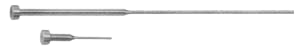
Optional: Pin sleeves are used in a case where there may be a screw hole in the part being manufactured. The pin will create the screw hole and there is a secondary sleeve that rides outside the pin. This allows for the pushing to take place on the lower flange of the screw hole where the part may shrink around the pin and the resulting resistance would otherwise create damage to the part.