EZ-LATCH
External Latch Locks
PREMIUM EXTERNAL LATCHES
PRECISION WITH EASE
Purchase on DME eStore

Precise Positioning For A Variety Of Different Molding Applications
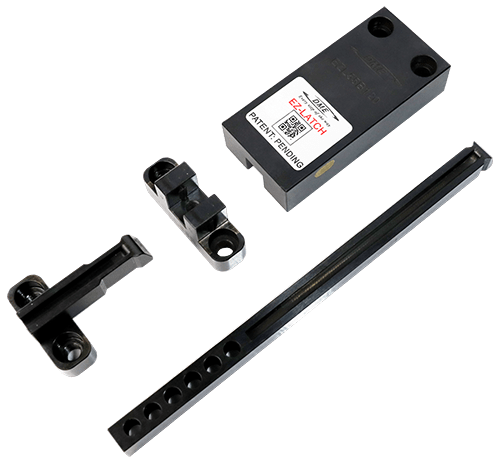
DME’s EZ-LATCH is the first truly universal external latch lock system. Most locks on the market are designed only for specific applications and require additional machining before they are ready for use making it difficult to select the right latch lock to correctly sequence the plates. The DME EZ-LATCH Lock, with its modular capabilities, addresses this limitation and, through its patented mechanical design provides safer and longer lasting performance.

Advantages Over The Competition

Providing A Controlled Sequencing Solution For Mass Production Molds
The DME EZ-LATCH Lock is the easy solution for all plate control application including 3 plate molds, 2-stage ejection, early plate return, both stationary “cavity” and moving “core” side ejection (in place of high cost hydraulic cylinders).

Unlike any other lock on the market, the DME EZ-LATCH Lock incorporates a positive mechanical lock avoiding the use of springs and/or friction devices a common source of product failure and even the occasional crashing of the tool. This safer solution provides a more consistent lock every cycle making it the preferred solution for mass production.
Designed For Ease of Installation
Its standard design makes it easy to install straight out of the box.
DME EZ-LATCH External Latch Locks
Positive and Precise Positioning of Floating Plates
Featuring
- Ideal for molds with floating plates, including stripper plates & 3-plate molds
- Floating plates are positively locked mechanically in place during mold opening and closing, preventing potential mold damage
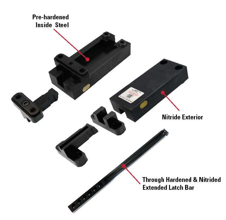
- Reliable long-life performance through its unique design and use of nitride diffused material, avoiding coatings that can wear off during use
- Allows faster cycle times due to mechanical action vs latch locks that rely on springs or friction to lock plates
- Simplifies mold design while improving design flexibility
- Designed and engineered to hold large loads while saving space inside the mold
- Optional long latch bar for greater stroke
Benefits
There’s a reason DME has added its new external latch locks to its EZ line of products:
- EZ – to install
- EZ – to sequence (time) plates
- EZ – to use on thin plates
- EZ – used for all plate control needs
- EZ – to disassemble & maintain
- Does not use springs, stripper/shoulder bolts or friction components
NEW – DME Reverse EZ-LATCH Locks
DME R-EZ-LATCH LOCKS PROVIDES PRECISE POSITIONING FOR TWO STAGE MOLDING APPLICATIONS
The easy and reliable solution to sequence your mold plates.
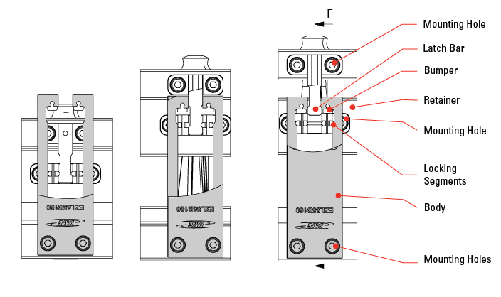
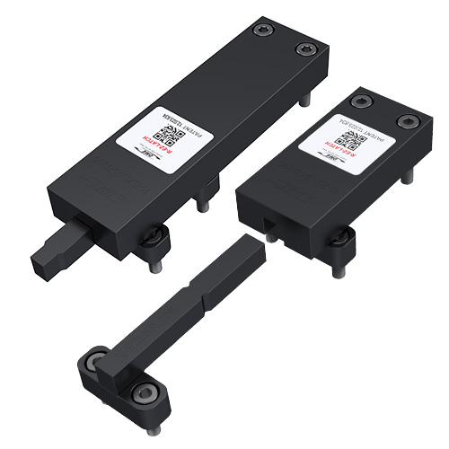
DME’s line of EZ-LATCH universal external latch lock system has been extended to include Reverse EZ-LATCH (R-EZ). All the same great features of EZ-LATCH in a simplified design which no longer requires the cam allowing a simplified installation and plate sequencing. R-EZ units are designed to allow precise control of plates in two stage applications with reduced travel. Just like the EZ-LATCH, R-EZ is ready to mount to your mold right out of the box with its modular capabilities and, through its patented mechanical design provides safer and longer lasting performance.
Multiple Segment Options
Depending On Part Geometry
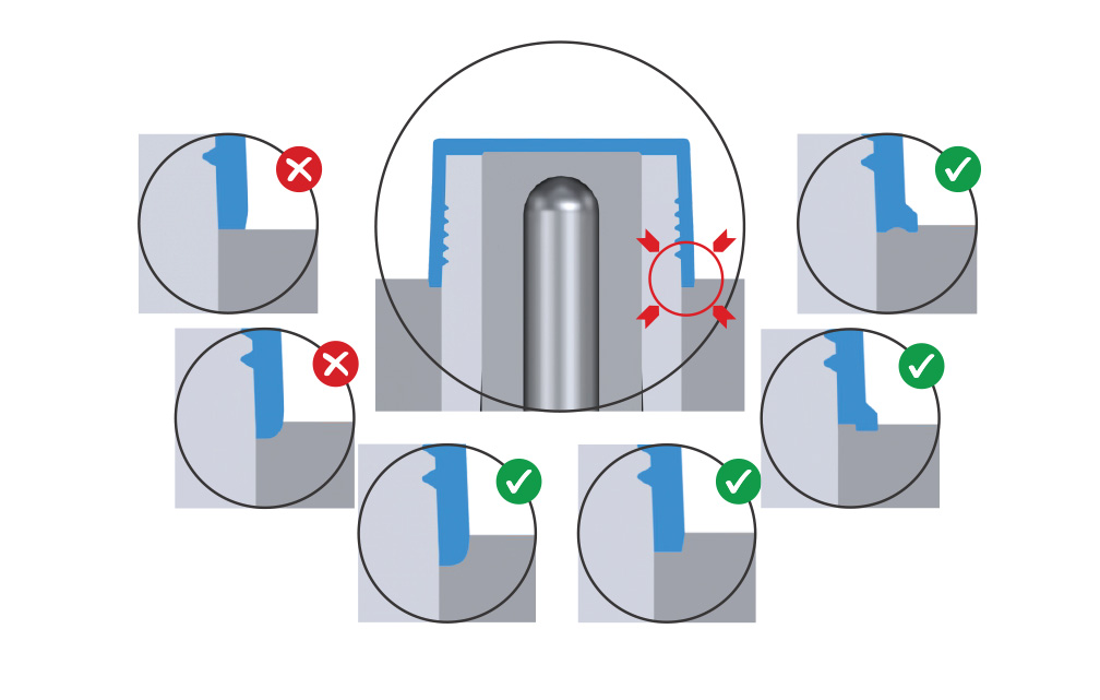
• Use tabs, ridges or indentations to lock parts in place, preventing movement during collapsing of the core.
• Sink parts into the B-side for increased hold area and stability.
• If the part has a radius at the bottom, avoid placing the parting line at the radius’s tangent point. Instead, sink the part further to secure enough bearing surface.
• Unsecured parts may damage the core and result in defective molded parts.
Application Examples
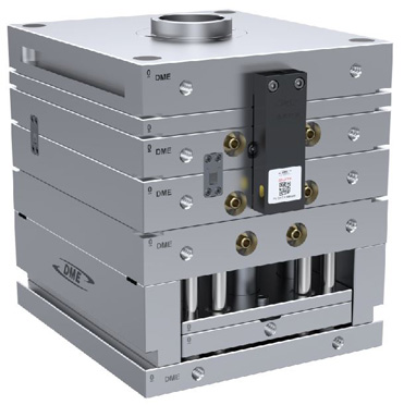
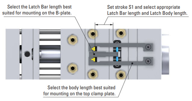
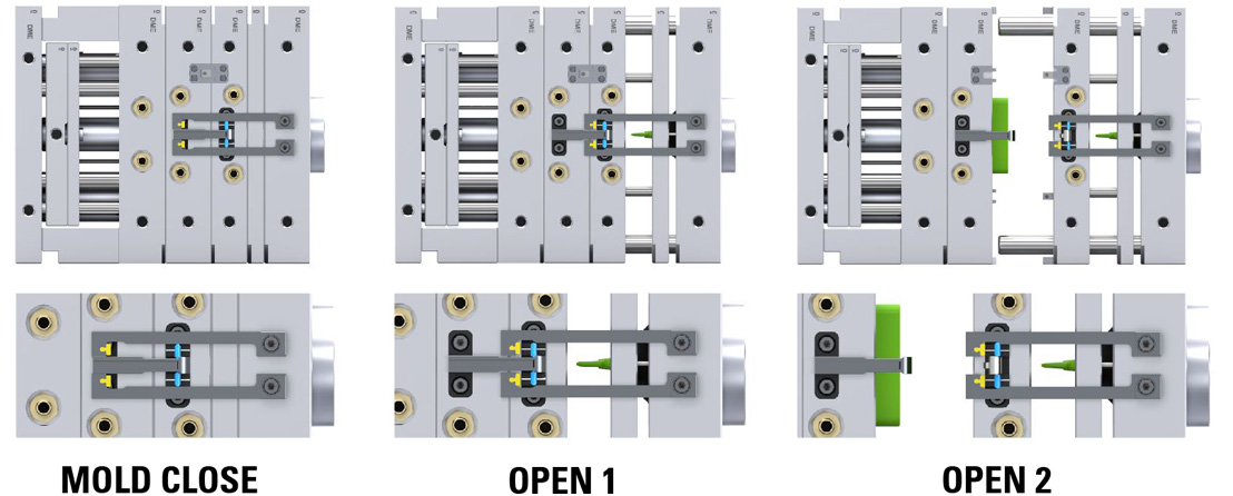
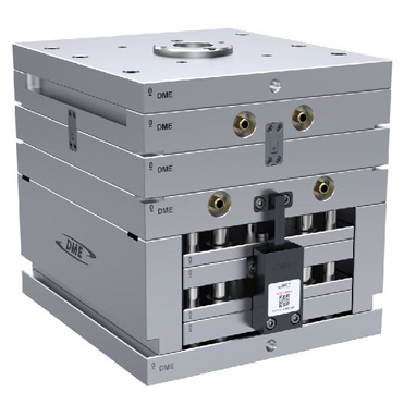
DME EZL Application Example – 3-Plate Control
Mounting Configuration
Latch Lock’s Body: Mounting on the top clamp plate (fixed plate).
Latch Bar: Mounted on the B-plate.
Retainer: Mounted on the A-plate, connected to the runner plate with a stripper bolt.
This setup allows precise 3-plate control during the parting line opening. Initially, the B-Plate and A-Plate move together for the designated stroke (S1) to effectively strip the runner from the part. Following this coordinated movement, the B-Plate disengages from the A-Plate, allowing the parting line to open. This sequence of actions can provide accurate control and efficient separation of the runner and part, which can enhance the overall efficiency of the molding process.
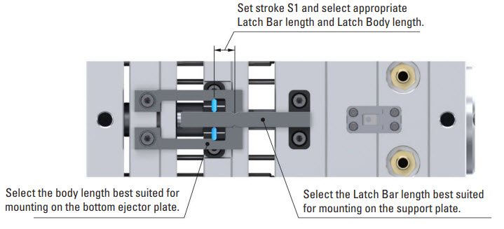
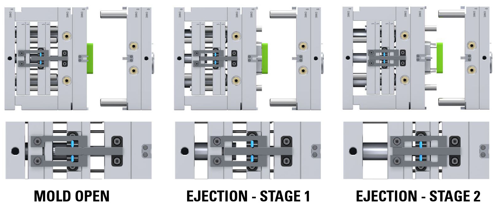
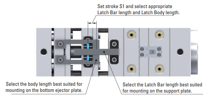
DME R-EZL Application Example – 2-Stage Ejection – Bottom Last Plate Control
Mounting Configuration
Latch Lock’s Body: Mounting on the bottom ejector plate.
Latch Bar: Mounted on the support plate (fixed plate).
Retainer: Mounted on the top ejector plate.
This setup allows precise control over the two-stage ejection process (bottom last). Initially, both ejector plates, spaced apart, move together for the designated stroke (S1). This synchronized movement is particularly important when lifters mounted on the top ejector plate need to disengage undercuts before the part can be ejected. After completing the initial stroke, the bottom ejector plate continues to move independently for the final stroke required to eject the part.
DME R-EZL Application Example – 2-Stage Ejection – Top Last Plate Control
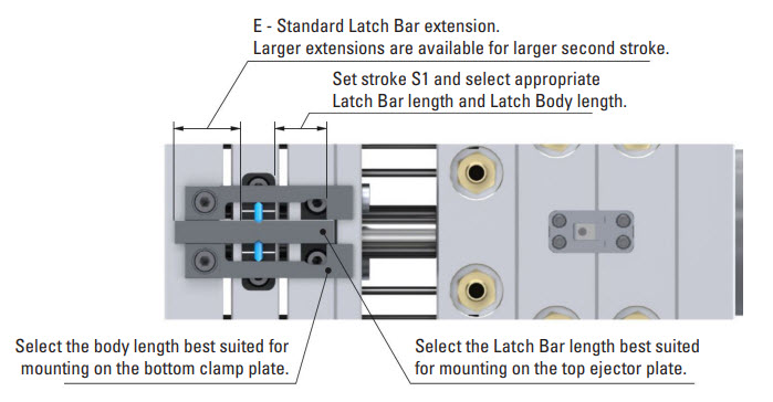
Mounting Configuration
Latch Lock’s Body: Mounting on the bottom clamp plate (fixed plate).
Latch Bar: Mounted on the top ejector plate.
Retainer: Mounted on the bottom ejector plate.
This setup allows precise plate control over the two-stage ejection process (top last). Initially, both ejector plates, place together, move for the designated stroke (S1). This synchronized movement is particularly important when lifters mounted on the bottom ejector plate need to disengage undercuts before the part can be ejected. After completing the initial stroke, the top ejector plate continues to move independently for the final stroke required to eject the part.
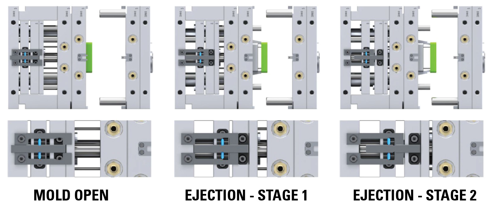
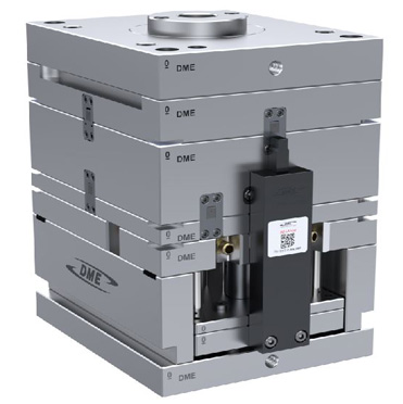
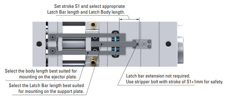
DME R-EZL Application Example – Bottom Last – Stripper Plate & Ejector Pin Plate
Mounting Configuration
Latch Lock’s Body: Mounting on the ejector plate.
Latch Bar: Mounted on the support plate (fixed plate).
Retainer: Mounted on the B-plate (stripper plate).
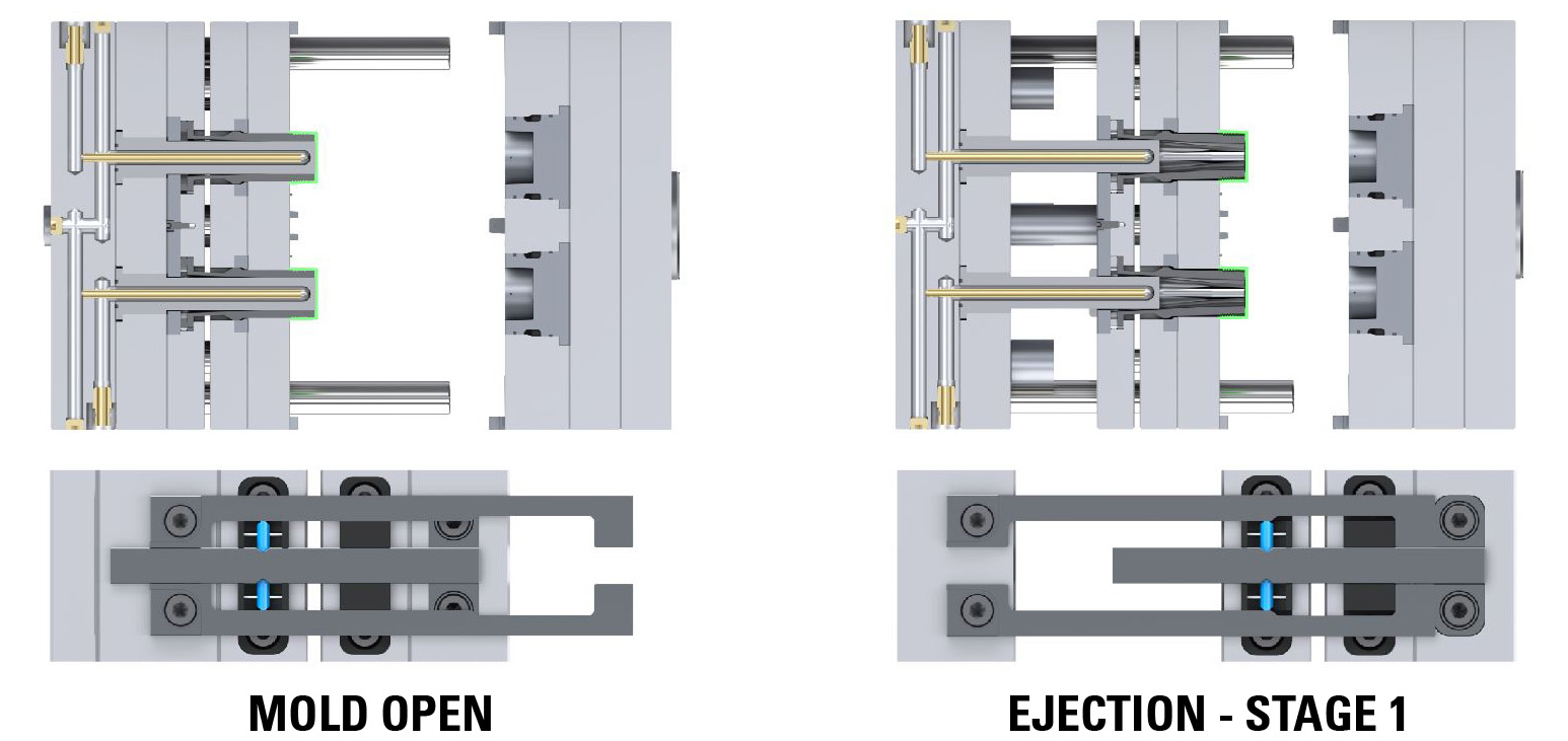
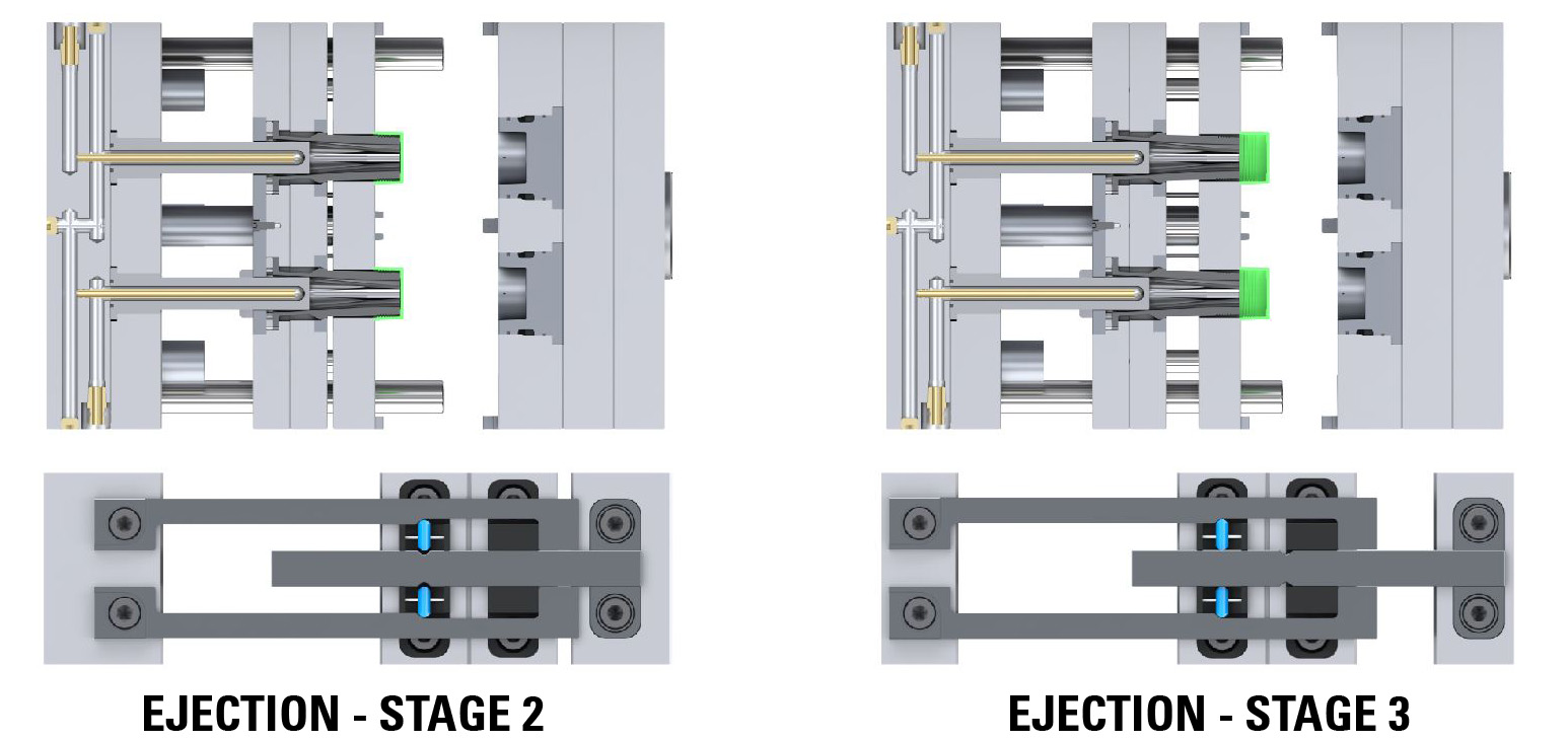
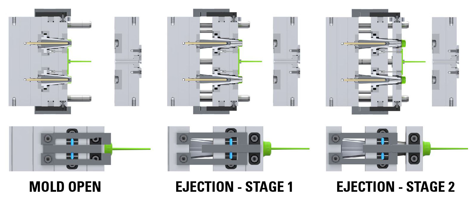
This setup ensures precise control of both the B Plate (stripper plate) and the ejector plate. Initially, these plates move together for the designated stroke (S1). This synchronized motion is especially vital in applications involving a collapsible core, where the core must collapse before the part is ejected. After this initial stroke, the ejector plate moves independently for the final stroke needed to eject the part using the ejector pins, ensuring a clean and efficient ejection process
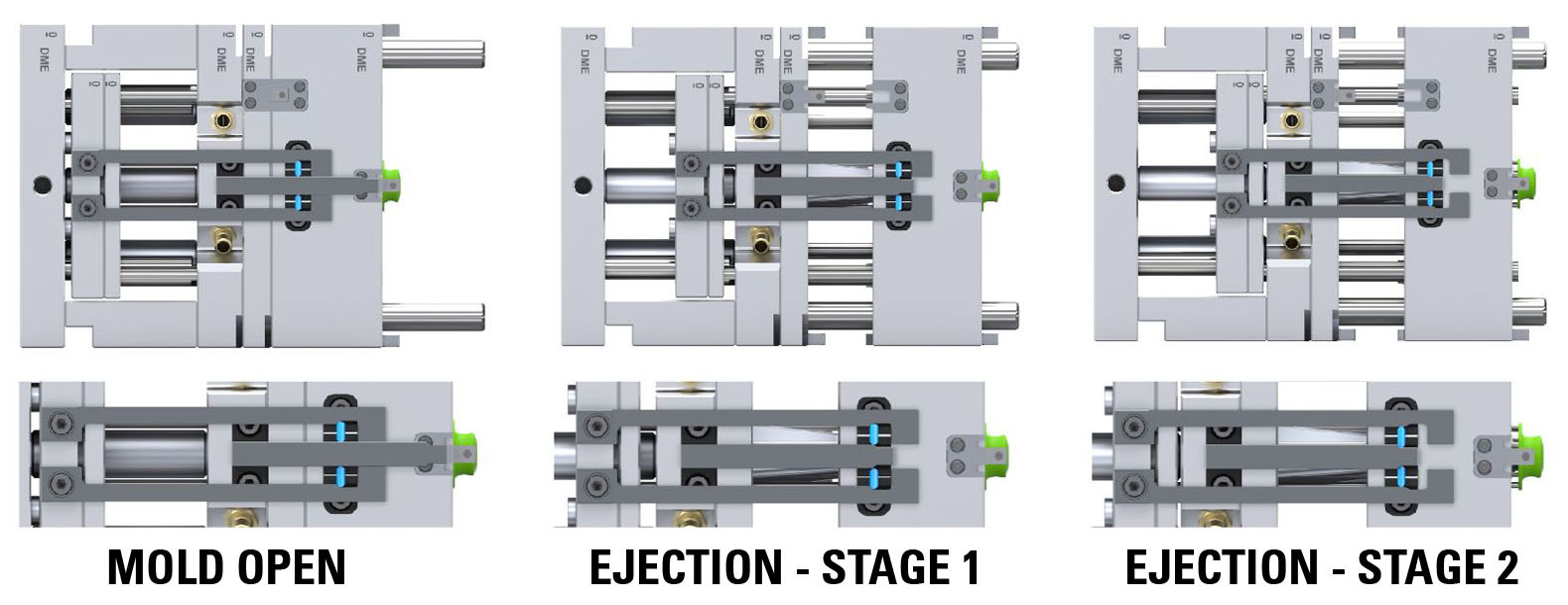
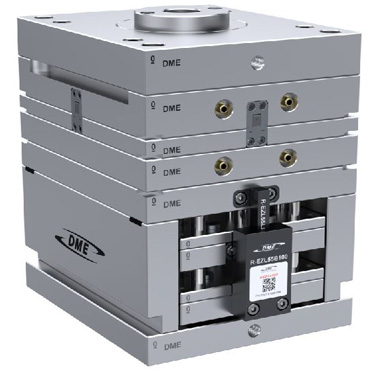
DME R-EZL Application Example – Bottom Last – For Collapsible Core With Insert On Top
Mounting Configuration
Latch Lock’s Body: Mounting on the bottom ejector plate, linked to the stripper plate.
Latch Bar: Mounted on the support plate (fixed plate).
Retainer: Mounted on the top ejector plate, linked to the B-plate.
This setup ensures precise control of the plates, crucial for efficient part ejection in molds with collapsible cores with an insert on top. Initially, both the bottom ejector plate (linked to the stripper plate) and the top ejector plate (linked to the B plate) move together for a designated stroke (S1). This synchronized movement is essential in applications with a collapsible core, where the core must collapse before ejecting the part. After this initial stroke, the stripper plate continues to move independently for the final stroke needed to eject the part, facilitating a clean and effective ejection process.

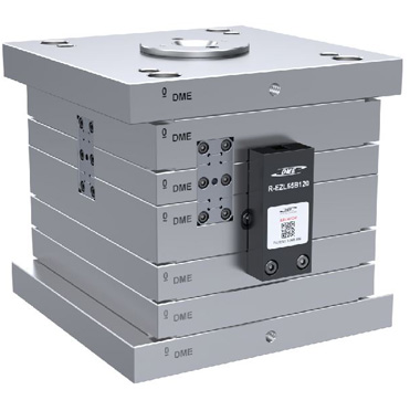
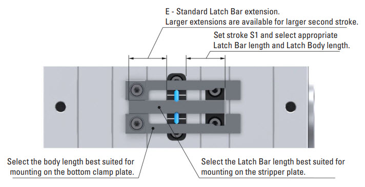
DME R-EZL Special Applications – S-Core Mold Base (No Ejector Box)
Mounting Configuration
Latch Lock’s Body: Mounting on the bottom clamp plate (fixed plate).
Latch Bar: Mounted on the stripper plate.
Retainer: Mounted on the B-plate.
This setup provides precise plate control essential for successful part ejection in S-Core Mold Bases (No Ejector Box). Initially, the stripper plate and B-plate move together for a designated stroke (S1). This synchronized movement is crucial in applications with S-Core molds, where the core needs to collapse before the part is ejected. After this initial stroke, the stripper plate moves independently for the final stroke required to eject the part, ensuring efficient and effective ejection.
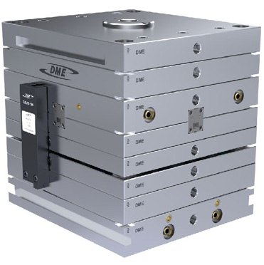
DME R-EZL Special Applications – DURA Core Mold Base – DC Latch Lock For DURA Core Mold BAse (Four Plate Control)
Mounting Configuration
Latch Lock’s Body: Mounting on the bottom clamp plate.
Latch Bar: Mounted on the stripper plate.
Retainer: Mounted on the B-plate.
Second Retainer:Mounted on the floating safety ring plate, located between the B-plate and the stripper plate.
This setup provides precise four plate control, essential for effective part ejection in the Dura Core Mold Base. Initially, the stripper plate, safety ring plate, and B-plate move together for a designated stroke (S1). Subsequently, only the stripper plate and B-plate continue moving together for a short distance to ensure the core’s collapse. Finally, the stripper plate moves independently for the final stroke required to eject the part, ensuring a smooth and efficient ejection process.
